


INTRODUCTION
Proper miter gear alignment is critical for ensuring reliable power transmission, smooth operation, and long-term durability of industrial machinery. Misalignment can result in excessive noise, vibration, premature wear, and even catastrophic gear failure. This in-depth tutorial provides actionable, step-by-step guidance for engineers, machinery maintenance teams, and automation specialists who need to achieve precise miter gear alignment for a wide range of industrial applications.
Understanding Miter Gear Function and Alignment Importance
Miter gears are a type of bevel gear, typically featuring equal numbers of teeth and a 1:1 gear ratio, designed to transmit rotational motion at a 90-degree angle between intersecting shafts. These gears are found in various industrial machinery, such as material handling systems, packaging equipment, and automation lines. The accuracy of miter gear alignment directly affects:
- Power transmission efficiency
- Wear and lifespan of gears and bearings
- Noise and vibration levels
- Overall machinery reliability
Achieving accurate alignment minimizes the risk of backlash, load unevenness, and premature gear failure. Whether working with straight cut, spiral, or custom miter gears, following a systematic alignment process is essential.
Common Mistakes and Problems in Miter Gear Alignment
Despite best intentions, even experienced engineers can make mistakes during alignment that compromise gear performance. The most frequent errors include:
- Neglecting initial inspection: Failing to thoroughly check shafts, keys, and gears for wear or damage can lead to future breakdowns even if alignment appears correct.
- Improper cleaning: Residual debris or old lubricant on gear teeth or mounting surfaces can result in uneven seating and inaccurate backlash readings.
- Inadequate measurement tools: Relying on visual estimation rather than precision measuring equipment leads to errors in shaft perpendicularity and gear mesh.
- Over-tightening fasteners too early: Locking bolts before confirming backlash and contact patterns limits the ability to correct issues without starting over.
- Omitting a test run: Skipping the post-alignment low-speed test run can mask subtle misalignment issues that only appear under dynamic loads.
Addressing these mistakes proactively not only extends gear life but also prevents costly downtime and repairs.
Tools and Preparation for Aligning Miter Gears
Before starting the alignment process, assemble the necessary tools and prepare the workspace. The following tools and equipment are commonly required:
- Feeler gauges and thickness gauges
- Dial indicators or digital indicators for runout measurement
- Straight edge and precision squares
- Torque wrench
- Clean rags and degreaser
- Soft mallet
- Marking pen and measuring tape
- Manufacturer’s datasheets or assembly drawings
Ensure the machinery is powered off, locked out, and adequately cooled before beginning. Clean the miter gears, shafts, and housings to remove any debris, old lubricant, or corrosion that could affect alignment accuracy.
Step 1: Inspect Components and Check Fit
Start by carefully inspecting all miter gear components, shafts, keys, and coupling elements for signs of wear, cracks, or deformation. Check that the gears fit precisely onto their shafts without excessive play. Damaged or worn parts should be replaced before proceeding. Confirm that shaft ends are free from burrs and that keyways align smoothly for proper engagement.
Step 2: Pre-Align Shafts and Mount Gears
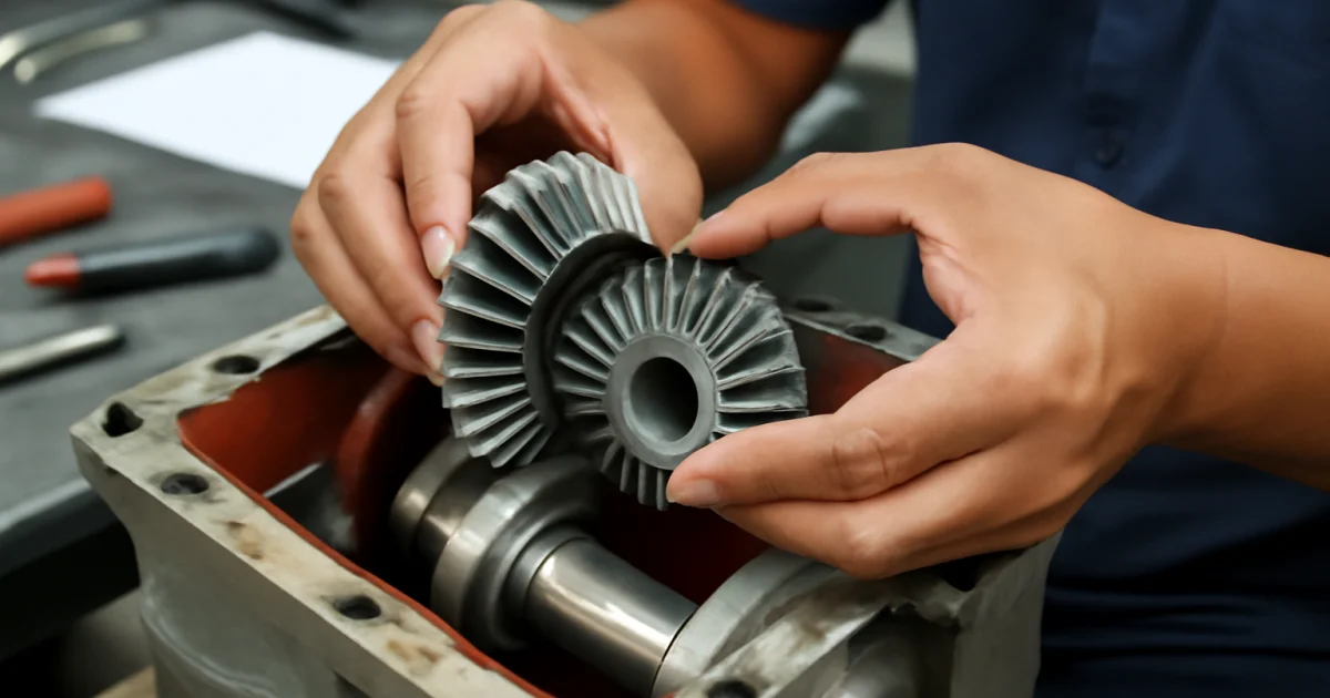
Position the shafts to be as close to perpendicular (90 degrees) as possible. Use a precision square or angle gauge to verify the intersection angle. Lightly mount the miter gears onto their respective shafts and loosely secure them according to manufacturer guidelines. At this stage, the gears should remain adjustable for fine-tuning.
For systems using couplings (such as MH coupling, HRC, or jaw couplings), loosely assemble the couplings as well, ensuring the hubs are not yet fully tightened. This flexibility allows for incremental adjustments during fine alignment.
Step 3: Adjust Gear Mesh and Backlash
Gradually bring the miter gears together by sliding the shafts or gears along their axes. Use feeler gauges to measure the backlash—the slight gap between mating gear teeth. Refer to the manufacturer’s recommended backlash value, typically specified in millimeters or thousandths of an inch. Adjust the gears so that the backlash is uniform around the entire gear circumference.
Rotate the gears by hand several times, checking for smooth, unobstructed motion and consistent backlash. If tight spots or excessive clearance are detected, reposition the gears incrementally and remeasure. Uniform backlash ensures even load distribution and reduces noise and wear.
Step 4: Fine-Tune Shaft Perpendicularity and Gear Contact Pattern
Use a dial indicator to verify that the shafts remain at a true 90-degree angle. Even a slight deviation can affect gear meshing and efficiency. Adjust motor bases, mounting plates, or shims as needed to achieve precise perpendicularity.
Check the gear tooth contact pattern by applying a thin layer of marking compound (such as engineer’s blue or Prussian blue) to the teeth of one gear. Rotate the gears together and observe the resulting contact pattern. Ideally, the mark should cover the central region of the tooth surface. If the pattern is off-center or uneven, make incremental adjustments to gear position and shaft alignment. Repeat this procedure until a balanced, centered contact pattern is achieved.
Step 5: Secure Fasteners and Verify Coupling Alignment
Once satisfied with the gear engagement and alignment, gradually tighten the shaft set screws, keys, and gear mounting fasteners in a cross-pattern to avoid misalignment. If couplings are used, align the coupling hubs using a straight edge or dial indicator to ensure minimal angular and parallel misalignment. Tighten all coupling bolts to the specified torque using a calibrated torque wrench.
Recheck backlash and gear rotation after fastening to confirm that alignment has not shifted. If changes are detected, loosen the fasteners and repeat the previous steps as necessary.
Step 6: Lubrication and Final Inspection
Apply the recommended type and quantity of gear lubricant—oil or grease—according to the machinery’s requirements. Proper lubrication reduces friction, heat, and wear, especially in high-speed or continuous-duty applications.
Conduct a final inspection of the gear assembly, ensuring that all fasteners are secure, safety covers are installed, and no foreign objects remain in the gear housing. Manually rotate the gears through several full cycles, listening and feeling for smooth, quiet operation. Address any irregularities before energizing the machinery.
Step 7: Test Run and Ongoing Monitoring
Restore power to the machine and run the assembly at low speed under no-load or light-load conditions. Monitor for unusual noise, vibration, or heat generation. Use vibration analysis or thermal imaging tools if available. Gradually bring the machine up to normal operating speed, periodically checking gear alignment and coupling condition.
After several operating hours, stop the machine and re-inspect the miter gear assembly for signs of abnormal wear or loosened fasteners. Periodic checks and preventive maintenance are essential for extending gear life and preventing unexpected downtime in industrial environments.
Practical Examples: Miter Gear Alignment in Malaysian Industry
In Malaysian manufacturing plants, miter gears are frequently used in conveyor drives, automated packaging systems, and heavy-duty processing equipment. For instance, a system integrator may need to align large miter gears within a gearbox to ensure seamless transfer of mechanical power between intersecting conveyor lines. In another scenario, a machinery maintenance team may replace worn-out gears in a packaging line, using the above alignment steps to restore quiet, efficient operation and minimize future breakdowns.
Companies like MT Gear & Engineering Services Sdn. Bhd. provide precision-fabricated miter gears, technical support, and engineering services to help clients achieve optimal alignment and maximize machinery reliability. Whether using standard or custom miter gears, following a disciplined alignment process is key to industrial success.
In-Depth Checklist: Miter Gear Alignment Process
- Before Alignment:
- Gather all tools and equipment
- Review manufacturer’s datasheets and alignment specifications
- Lock out and tag out machinery
- Clean all gear and shaft surfaces
- Inspect gears, shafts, keys, and couplings for wear or damage
- During Alignment:
- Verify shaft perpendicularity with a precision square or dial indicator
- Mount gears loosely and incrementally adjust for optimal mesh
- Measure and set uniform backlash at all positions
- Apply marking compound and inspect tooth contact pattern
- Fine-tune shaft and gear positions as needed
- Tighten fasteners gradually and in a cross-pattern
- Align couplings and secure to specified torque
- After Alignment:
- Lubricate gears according to manufacturer’s recommendations
- Replace safety covers and check for loose objects
- Perform a manual rotation and listen for irregularities
- Conduct low-speed, no-load test run
- Monitor temperature, vibration, and noise during operation
- Re-inspect after several hours and record findings for future maintenance
Advanced Considerations: Aligning Miter Gears in High-Performance Systems
In high-speed, high-torque, or precision automation systems, the service alignment requirements are even more stringent. Factors to account for include:
- Thermal Expansion: Operating temperature changes can cause shafts and housings to expand, altering alignment. Allow for thermal growth by referencing specifications and, if possible, aligning at typical operating temperatures.
- Dynamic Loads: Varying loads during start-up or production cycles can stress gear teeth and shift alignment. For critical systems, consider dynamic alignment checks using load cells or vibration monitoring during real operation.
- Bearing Condition: Worn or poorly lubricated bearings can introduce runout, affecting shaft and gear positioning. Always assess bearing play before finalizing alignment.
- Custom Gear Designs: Spiral or hypoid miter gears may demand specific axial or radial positioning. Consult with the gear manufacturer for precise alignment protocols in custom or high-load applications.
Implementing these advanced measures can dramatically improve the lifespan and performance consistency of this option-driven systems.
Troubleshooting and Maintenance Tips
Even after careful alignment, issues may occasionally arise over time. Proactive troubleshooting helps catch and resolve problems early. Consider these tips:
- Listen for changes in noise profile (new rattling, whining, or grinding)
- Monitor gear and shaft temperatures for unexpected rises
- Check for oil leaks or loss of lubricant at gear housings
- Inspect gear teeth visually during scheduled maintenance for pitting, scoring, or abnormal wear patterns
- Use a vibration meter to compare baseline readings with current operation
- Document all findings and corrective actions for future reference
- Engage with professional gear service providers for advanced diagnostics or realignment if persistent issues occur
Conclusion: Achieving Long-Term Reliability with Proper Miter Gear Alignment
Precise this guide alignment is a cornerstone of reliable power transmission in industrial machinery. By systematically inspecting components, setting correct backlash, fine-tuning shaft positions, verifying gear contact patterns, and performing thorough testing, engineers and maintenance professionals can ensure trouble-free operation and extended gear life. For complex gearboxes or specialized transmission systems, consulting with experienced gear manufacturers or engineering support providers, such as MT Gear & Engineering Services Sdn. Bhd., delivers added assurance and technical guidance.
Investing time in proper alignment pays dividends through quieter operation, reduced downtime, and lower maintenance costs—critical factors for today’s demanding industrial and manufacturing environments.
Frequently Asked Questions
What are common signs of miter gear misalignment in machinery?
Typical signs include abnormal noise (such as grinding or whining), excessive vibration, rapid or uneven gear wear, increased operating temperatures, and visible damage to gear teeth or shafts. A properly aligned miter gear system should operate smoothly and quietly. If you notice any of these symptoms, inspect and realign the gears promptly to prevent further damage.
How do I measure backlash in a miter gear assembly?
Backlash is measured by gently rocking one gear back and forth while holding the mating gear stationary, then using feeler gauges or dial indicators to assess the gap between gear teeth. The correct backlash value should follow the manufacturer’s recommendation, which is typically specified in the technical datasheet. Uniform backlash is crucial for minimizing load shocks and ensuring even gear wear.
Why is correct shaft perpendicularity important for miter gear performance?
Miter gears are designed to transmit motion between shafts set at exactly 90 degrees. Even slight deviations from this angle can lead to improper gear meshing, uneven contact patterns, increased wear, and loss of power transmission efficiency. Always use precision measuring tools to check and set shaft perpendicularity during alignment.
Can I use the same alignment process for straight cut, spiral, and custom miter gears?
While the general alignment steps are similar for straight cut, spiral, and custom miter gears, there may be specific considerations based on gear design and application. For example, spiral miter gears may require more attention to axial positioning due to their helical teeth. Always refer to the manufacturer’s guidelines and consult with gear specialists for unique or high-load applications.
Where can I find precision miter gears and technical support in Malaysia?
MT Gear & Engineering Services Sdn. Bhd. is a reliable provider of precision miter gears, technical support, and engineering solutions in Malaysia. The company offers standard and customized gears, along with after-sales support, to help clients achieve accurate gear alignment and dependable machinery performance.
Need Expert Help with Miter Gear Alignment or Custom Gear Solutions?
Trust MT Gear & Engineering Services Sdn. Bhd. for precision miter gears, expert alignment guidance, and reliable engineering support for all your industrial machinery needs. Our team delivers tailored solutions, high-quality gears, and technical expertise for manufacturers, automation integrators, and maintenance professionals across Malaysia. Ensure your equipment operates at peak efficiency—contact us for a consultation or to discuss your next project.